 |
| Manufacturers |
| Other List |
| Freya Radar |
| Wurzberg Radar |
| Heliofly III |
| Ohka |
| Home |
William Moore
This in depth build review is being done because not many
people
will buy this kit because of it's cost ( $85 US from Silverbird OR $140
AUD FROM NKR MODELS ) and it's subject matter, but I love it so I'm
indulging myself .
Wurzburg Riese radar - Extratech 1/72 $85 US
If you are a Luftwaffe nightfighter enthusiast then this radar
set will enthrall
you , if not it will seem too expensive but this is a kit I love. Yes
at $85 it is pricey but it's got a
hell of a lot of brass . The kit is packaged in a nice box slightly
bigger than Huma's Me P1106 one
with a nice photo of the completed kit on the side . What becomes
immediately apparent on
opening the box is that this is a great kit . There are 2 X 5 inch
square brass sheets with the basics
of the aerial array and a 5X3 inch fret for the ladders and gears . The
main body pieces are resin
with large moulding blocks to remove which will be fun !!!. The rest of
the construction is mostly
assembly of the brass in the 10 step instructions . Having looked long
and hard at the instructions
there appear a couple of unclear areas but I hope to do this kit soon
and report back on how it
goes in great depth - hopefully no swear words ! See the Miscellaneous
section for the rest of the tale.
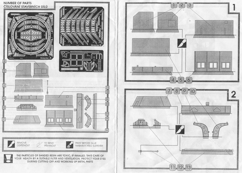
29/6/97 Sunday - The first 2 stages of the instruction sheet cover cutting out the main resin pieces. I started the kit finally on Saturday and got out the base piece. This is a large six sided piece with quite a large moulding block. At this stage I'd like to point out a few things - If you don't have a razor saw and a breathing mask then buy them immediately. The amount of resin dust generated by this kit is quite large - certainly much more than the average Planet a/c kit , you'll also need a broom and pan to clean it all up. This kit is serious lung damage territory if you're too macho to wear a mask.
The moulding block must be removed by cutting each side as far down as possible. I found my saw was just slightly too small and I still had to remove some bits with a scalpel. Beware if your saw blade is too small as it can hit against the side of the base and scratch this , the other thing to be aware of is to keep each cut at the right angle or you will start cutting into the base on the next side along from the one you're cutting. After I cut away all the bits I then smoothed off the base mostly by scraping a scalpel across the surface and then finally sanding on a flat piece of sandpaper . All this took about 30 mins to do.
I then moved on to doing the turntable which also has 6 legs . Be careful with this as the bottom is very easy to snap off. I then cleaned up all the other bits including the radar support arm which is also a bastard . All up I spent about 6 hours cutting out the resin pieces and trimming and sanding as appropriate. The walls etc. for the building are very easy to do with the inside surfaces to be painted black to avoid that see through effect on the windows . You also need to add clear plastic for the windows from your own supplies.
13/7/97 Assembly of the walls is quite straightforward and a little Milliput is all that is needed around a few of the joints. You may have to cut the base slightly to fit . At this point I had another peruse of the instructions and noticed that in stage 9 that a piece of etched brass was added to the turntable to represent the teeth on the gears for turning the whole unit. Given it's somewhat out of the way position on the final assembly I decided to add this now and detail as appropriate. Logically the ends of the teeth should be a shiny steel colour with the insides a blacky colour to represent the build up of grease used to lubricate the teeth. I glued this all to the six sided base with a combination of superglue on the inside for strength and PVA on the outside for gap filling with a little bit added later to provide a better looking join between these 2 parts. The inside of the base should be painted in black to avoid showing the cream resin interior.
28/7/97 After yet another break I had a quick think about how I was going to display this kit. Unfortunately the word " diorama " sprang to mind but I was stumped as to details. My mate Simmo had recently lent me a copy of 'Wings of Fame ' Volume 5 and I was skimming this as usual . Well I got to the section on photo reconnaisance Spitfires ( how exciting !!! :-) wry grin and suddenly saw a photo of a Wuerzberg with a man next to it that the British used to scale the station. This looked nice and easy - a circular concrete base with sand around it and 1 figure to add and then I thought of the old clock face I had been saving for a diorama base and so the final product was born.
Varnished the base with Estapol then added cement to the base which I left to dry for 2 days and then patched up any faults . I used a chinese takeaway container lid inverted to provide a mould for this base as it was around the right size. This didn't work out as well as I would have liked so back to the drawing board . Casting about for a replacement I finally settled on two old CD ROM's of games I didn't like and stuck these together and thence to the base After this sand was added by pouring this over PVA glue spread over the rest of the base area . I then smoothed a small layer of Exterior Spakfilla mixed with lots of PVA over the CD's after scoring them for a better grip and attached the base and turntable to this after painting in Aeromaster acrylic RLM 66. The PVA made the Spakfilla more rubbery and less prone to cracking than the cement and the colour looked right. Later when applying a wash to the rest I also did it lightly to here also.
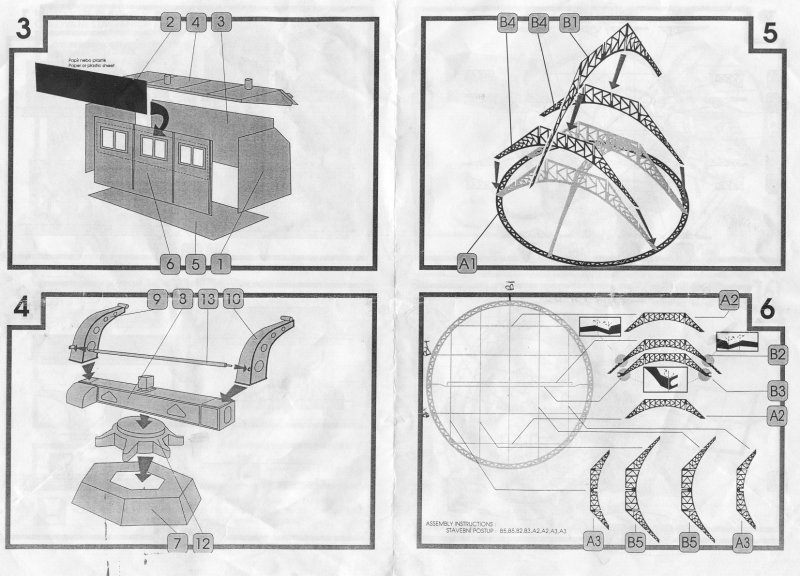
At stage 4 I would advise not adding parts 9,10 & 13 which are the arms for the radar support as some fitting and jiggling may be needed later.
Stage 5 - Brass and more brass.
At this point I was glad to see the last of the resin and all the sanding there but was dreading the brass. I've only ever used a couple of brass sheets for detailing cockpits with mixed success. Such a huge amount of brass daunted me given the cost of the kit and how easy I thought it would be to screw up, fortunately I was wrong .
The first thing to do is get out the 3 sheets and prime them - I used Mr Primer from Gunze - smelly but effective . This not only primes but also seals the brass against tarnishing. To construct I used mostly Superglue but occasionally 5 Minute Araldite for extra strength. I also used surgical gloves to reduce grease on the parts as well as 3 new No.11 scalpel blades for cutting. Additionally I cut everything on a piece of cardboard from the kit on top of a kitchen tile . I found that despite advice to use files to clean up burrs from cutting that using a scalpel blade as a file worked better especially as it didn't seem to bend the metal as much.
When I first started I put the two B4's up first and then supported these whilst drying and then went to add B1 as a cross piece which was very fiddly . At this point a lightbulb finally went off and I realised the kit was designed as an integrated structure and that the grooves cut at various places were to aid joining much like a joint in woodwork . I then assembled the 3 parts together and found that together they formed a strong structure . As you add more parts to the kit you discover the dish getting stronger yet it still looks delicate.
Stage 6 - The spiderweb starts
The instructions here give a recommended order which should be followed. To note is that B1 from stage 1 is located at 12 o'clock on this diagram and the B4's at approx 8 & 10 o'clock . Parts B2&3 fit together at the ends but should not be glued till later as the arms from the base attach at this point. Incidentally these arms need to be reduced on the inner side as they are too wide for the C formed at the end of B3 .
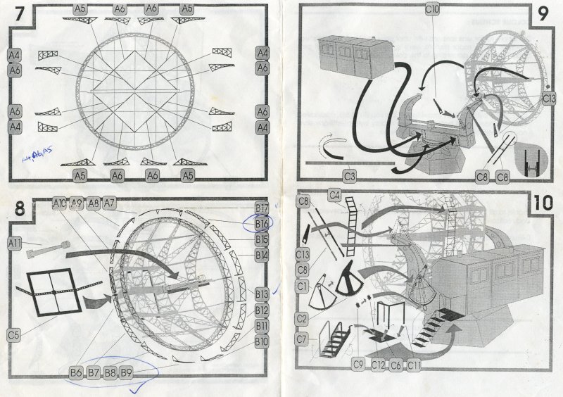
Stage 7 - More web
The instructions are fine here except I'd recommend starting with the A4's as these were hard to fit . I needed to cut both ends on 2 of these to achieve a fit but this is not noticeable . The A6's followed by the A5's are next and that finishes this stage. Some jiggling around may be necessary for good fit here . The view in this diagram is from the front.
Stage 8 - A finished web
This is the most fiddly step . First add the centre square . I believe this is to be added to the back with the "tread" etching on the outside ie not the concave centre bit where the resin focus is to rest in . I decided to leave the focus off till later to avoid knocking it. Now comes the tricky bit -16 pieces of "fencing" which stick out at 90 degrees to the rim of the dish . Each one has to be bent to a slight curve which is best done by a pen on a bed of newspaper to gently give this curve ( Thanks Simmo ) then carefully attached. I still found that I was over in length so I had to trim at halfway and at the finish. This was probably because I didn't always manage to get the join really tight , something that experience would help . I used a bit of Kristal Kleer suitably thinned to fill any gaps before painting. I suggest this be done in 3 or 4 sessions as it is quite exacting and the last thing you need at this point is to get frustrated - slow and steady is best .
Stage 9 - Joining up
The first thing to do is add the cross beam on top of the turntable which has a strip marked over the writing. You should have already added the teeth much earlier . Next add the cabin .Once this is done add one of the support arms . Once this is firm , test fit adding the other arm as well as the connecting rod and the actual radar dish . On mine I had the base of each arm project to the side of the beam by approx 1mm and slightly to the front otherwise the rod will not fit or the dish. A bit of jiggling may be needed and the first arm should probably be added using white glue to enable some repositioning. The radar dish as mentioned earlier has two C hooks which must also be test fitted.
Next up is the small fiddly bits from the last sheet of brass . I prepainted these in RLM 66 and attached these whilst also spraypainting the radar dish . The airbrushing should be done in a few goes so as to reduce paint buildup and preferably off the kit.
The small parts were added last and a little jiggling is needed to fit these . Add C10 & C13 first ( with white glue ) then adjust so the two C8's can fit . The diagram here attempts to illustrate that each C8 goes on one the outside of the other two parts..
Stage 10 - The end - Now at this point I thought I was home and hosed as I only had to add the stairs which I thought would be easy . I had forgotten that the main actuating arm also needed adding . This is virtually a repeat of the previous para except that C9 &C12 with the gear teeth must be added . I ended up using a small piece of sprue around 1.5mm long to prop the teeth out to meet the main gear from parts C1&2.. Add the inspection ladder to the dish. Next step is the stairs and landing . First add the landing . This needs a little moving around to ensure a good fit . Folding the rails is also a little tricky. I recommend adding some white glue on the rails to remove the flat cross section and give one more circular. Next up is the stairs. Again before cutting out add white glue to build up a circular cross section. This bit is really tricky . You need to bend up the two side sections so that they are parallel to each other . You then need to bend each stair tread so that they appear flat then glue in position . As each stair tread is attached by two very thin pieces to the sides you will inevitably have at least one of the treads hanging in space. The key here is calmness and a steady hand .Before you bend each stair hold the whole structure against the landing to get an idea of the angle the stairs should be at. this is fiddly but the finished product looks great .
Final diorama bits - I actually sprayed another couple of coats of RLM 66 on after masking off my base. This eliminated any bits that were still showing brass and integrated the whole structure . I also applied a few light washes as well as some drybrusing on the gear teeth and the stair treads. The last thing to add was the figure which was painted very simply . The photos below do not do justice to this kit.
I must say this is one of the most enjoyable kits I've done in a long time. It was a challenge to do but the instructions and thought put into the kits layout makes it doable by a patient average modeller. It also has that essential "oh - ah " factor when shown to people you know - even non-modellers.
Below are the instructions and various shots during building. I've also included a picture of a radio telescope here in Australia built by MAN in 1961 - nice to see all that building experience on large steel dishes didn't go completely to waste ! |
 |
 |
 |
 |
|
 |
 |
 |
 |
 |
 |