 |
| Manufacturers |
| HO
List |
| Ho 229 |
| Ho VII |
| Ho XIII |
| Ho XVIII |
| Home |
Various versions
Ho 229 1/48 - Dragon - Steve Stohr
I used the paint scheme that is shown on the box top. I used a mix of tire black and black on the bottom, (I never use pure black or white on anything) and the top was RLM 76/75. I did all of the undercarraige and wheel wells 02, and the cockpit 66.
Fit was pretty good for the wing halves, the wing to fuse fit took a thin ribbon of putty, but nothing too bad. The nose to the fuse took some doing to get it looking good. I had it all done, and painted the bottom, and the top seam cracked open, so I had to do that part twice. Overall I liked the kit. It was my first DML kit that I have built, and I have just about every other kit that they have done still in the closet.
I didn't keep track of the time spent on the kit, but I suspect that it took me somewhere between 12 and 15 hours to build, maybe a little bit less.
Ho 229V1 - AV Models - 1:72 - John Clarke
This was the unpowerd first prototype of the Ho IX / Ho 229 flying wing fighter. This aircraft flew successfully in late 1944.
This is a multimedia kit comprising resin, white metal parts, a generic brass photo etched detail sheet, a single vacuum formed canopy all packaged in a segmented plastic bag. The kit also contains decals & instructions all packaged in a box.
Although the surface finish is good, the wing profile does not match the fuselage center section wing profile. This has required quite a bit of filler to join the wing / center section together.
Although the standard of this kit is not up to the same standard as "PLANET" resin kits, The moulding on this kit has improved over their earlier offerings.
Other than the problem outlined above the kit should go together well & will fill an empty space in my collection.
Available from. NKR models in Australia Hannants in England
Horten 229V7 PM Models - 1/72 Injection Moulded - Fred Bultman
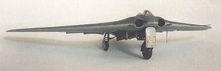
The Horten brothers, along with Walter Lippisch and Jack Northrop,
were pioneers in designing
flying wing aircraft. In 1944, the Hortens received a contract from the
RLM to build a
prototype of their Ho IX twin jet single seat fighter design. This
aircraft first flew in late 1944,
and the RLM was significantly impressed for it to issue a production
contract and the type
classification "229". Gotha was designated as the manufacturer, which
is how the controversy
arose as to whether it is a "Ho 229" or "Go 229." Eight aircraft were
partially completed. The
V7 prototype was two be a two seat Nachtjaeger armed with four 30MM
cannon and a FuG 244
"Bremen" short-wave radar. The antenna for this radar fit into a nose
cone much like modern
fighter planes. I cannot verify that the V7 was actually built, so this
is definitely a "Luft '46"
aircraft.
The 1/72 scale PM Models kit is imported from Turkey and appears to be a reissue of an older Huma kit ( ??? - William ) . The local retail price is about $9.50US. The kit is moulded in gray styrene, about 20 parts. The parts are clean, with minimal flash or mold marks. The canopy is moulded clear plastic and there are no photoetch parts. In fact, except for the seats there is no interior detail. Ah, the joys of scratchbuilding (sigh). The decal sheet has only the four wing crosses, so a trip to your decal stash will be necessary if you want to add fueling point triangles and/or squadron markings. I still think they would have put swastikas somewhere, even without a rudder. The instruction sheet is good, with clear layout views and the English translation is not garbled. Only problem is that they forgot to show where to put the DF aerial. I suggest putting it under the nose, just in front of the nose wheel. The single seat version has it behind the cockpit on top of the fuselage. The styrene is slightly soft, so be careful trimming sprue points. The body of the aircraft is moulded in upper and lower halves, with good fit and alignment. The panel lines are engraved and subtle. This is a surprisingly large aircraft, almost as big as my Hawker Typhoon.
The main landing gear is set well back so that nose weight is unnecessary. The big nose wheel looks out of proportion but matches photos of the real thing. The landing gear doors are provided in three pieces. This is OK if you are building a gear up model. Unfortunately, I wanted gear down so I needed to cut the three pieces into nine pieces. The cut lines are marked on the doors, but are raised lines. Use a new knife blade. The surgery was successful.
When cleaning up the jet intakes in the fuselage halves be careful and hold the halves together while you trim. I will have to fix an oops with some putty.
The second task was building an interior. I cut masking tape seat belts and applied them to the seats. Dots of white glue dry flat to make the buckles. I made a control column from stretched sprue, bent to a very shallow 'z' shape, and dipped one end in white glue (let it dry between dipping to build up the pickle. I also cut rudder pedals out of .10 styrene sheet but these are not visible so not worth doing.. I made a box (about inch square) of .10 sheet with a little disk on top to simulate the radar unit. This is placed immediately behind the pilot's seat. The same material was used to make an instrument panel for the pilot.
As model building is meant to be my hobby away from my hobby, the therapeutic benefits are more important than that passion to get every detail perfectly to scale.Monogram Close-Up 12 Horten 229 by David Myhra
Monogram Aviation Publications 1990
ISBN 0-914144-12-X
Air Enthusiast 39 May-August 1989 pg 1 - 18 Horten Exotica
William Caple & Co. Ltd.
Flying Wings of the Horten Brothers by Hans-Peter Dabrowski
Schiffer Publishing Ltd. 1995
ISBN 0-88740-886-9
The Horten Flying Wing in World War II by Hans-Peter Dabrowski
Schiffer Publishing Ltd. 1996
ISBN 0-88740-926-1
(From GERMAN JETS IN WWII ( http://torgo.astro.ucla.edu/german_jets.html))
I did not find a drawing of the V7 on the Internet so it is impossible to say how accurate the kit is. The fuselage depth definitely looks too shallow. Anyway, back to work..
I painted all of the cockpit area in light gray. (Does anyone know the RLM number for interior gray?-[ RLM 02 but for cockpits I normally use RLM 66 for late war a/c - William ] ) The instrument panel is black with white dials dotted on. I did the seat belts in olive drab and the buckles in dark metal. The radar screen is a translucent dark green. Other details were dark gray for contrast and the joystick pickle is red. I installed the jet intake cones before joining the fuselage halves. This was a mistake as they are slightly off center. Better to install them later with tweezers. The rear exhaust cones were painted dark metal and the area around them in black. When first installed they sat too low in the opening. I cut .040 styrene shims, glued them to the bottom fuselage, and mounted the cones on top. I had to trim the top of one cone to get a good fit of the fuselage halves. This also the best time to drill out the four cannon ports and install the cannon barrels. These barrels protruded on the single seat fighter. About 1/8 inch seems right using straight pins.
Why is it that whenever you test fit fuselage halves they fit perfectly, but when you glue them they don't? Actually, they fit well with just a bit of mismatch on the trailing edge of one wing. I scraped all the seams, sanded, primed, MASKED the cockpit, (I think that DUPLICOLOR gray auto finish primer is great .) and then did some minor filling by the jet intakes and the tip of the 'tail.' Get the jet intakes as round as possible. Also, smoothing the seam between the gun barrels was a bit tricky. I also drilled a hole on the fuselage underside, halfway between the nose and the wheel well for the Radio DF loop. I think it looks better here than to mount it on top behind the cockpit.
I originally planned to airbrush this model. However, an accident to my air tank put the kybosh to that plan. The topside is painted (first) in a light gray (RLM 76) and the underside is black (RLM 22). I use a inch chisel brush to apply three or four very thin coats of paint, letting it dry between coats. The camouflage pattern is a medium gray (RLM 75) and is applied by using a bullet shaped stiff bristled brush. (A round pencil eraser also works.) Stamp the brush on a piece of paper a few times until the dot becomes raggedy and then stamp the model. This will produce nice, irregular dots. Stamp at random all over, and then fill in, to avoid a too even appearance. (This job is definitely easier with an airbrush!)
I painted the outside of the jet intakes in bright red. A undercoat of white makes this job easier. I also painted the running lights. The wheel wells are interior gray and the radome is black. I used a sharp 4H pencil to draw in the panel lines and control surfaces. Since the underside is black, I didn't bother to do it there. I dry brushed (a very dry brush) some medium gray over the underside to relieve the monotony and bring out a bit of the detail..
When everything was painted and dry, I spayed with Gloss Cote and let it dry. I took the decals from a Hasegawa FW 190D and from a DML ME P1101 kit. There are white balkenkreuz on the wing underside, black balkenkreuz on top, two black swastikas on the 'tail,' a unit crest on each side of the nose, the number '7' in red on the outside of the jet intakes, and fuel triangles on upper wing gas caps. Again after everything dried, I sprayed with Dull Cote. I painted the nose radome and the jet intake cones with clear semigloss.
This is a good time to paint up the landing gear and landing gear doors. Tires are medium gray and the tread is a lighter gray. The struts are interior gray, with some bright steel for the moving parts. The fit is good, with a little trimming of the peg that holds the nose wheel in place. Also, the main wheels have a right and a wrong side. Test fit before you glue.
At this point I removed the cockpit masking and touched up any spots that needed it. The canopy itself is thin, very clear and fits very well. I decided not to polish the canopy but just wiped it clean, and then hand painted the simple framing. Any little paint slop can be scraped off with a sharpened toothpick. Then I glued it on with Kristal Kleer and touched up the paint around the base of the canopy.
Glue the DF loop on and paint it dark metal. Attach the landing gear doors, and your Horten 229 Nachtjager is finished. I did not weather mine because I wanted a factory fresh look.
After I wrote this article I found out that the V7 prototype was the two-seat trainer. The night fighter was designated '229B.' I think the PM kit is the night fighter because it has a radome nose.
Fred Bultman
Articles of interest
John Clarke
Ho 229 - Dragon - 1/48 - Article - culled from discussions
Who among you have had trouble getting the ho229/ho229 cockpit front panel into place? Watch those wing joins. Try building the top half wing and fuse and the bottom half wing and fuse. That way you get a perfect hassle free wing join as it is much easier to join the completed top and bottom halves.
Jamie
I just got my kit last week and spent a lot of time
comparing it
to the excellent cutaways and
details that I have in the Monogram's "German Aircraft Interiors" book.
A few comments:
Dragon seems to have cut a lot of corners in that kit, but then again
that may all sound like
nitpicking. The interior of the cockpit is a bit different in Arthur
Bentley's drawings, the side
consoles are absolutely bogus in the kit, in fact they were very
different with lots of levers and
shutters on the left side. On the right side, there was a large box
with the main circuit switches
all missed by the kit. There was no wall between the frame work of the
cockpit and the engines.
There also was no floor, the seat sitting on top of a X shaped frame,
right above the wheel well.
There was also no panel behind the seat, this being attached to a
couple of rails running from
the top to the bottom tubular spars. The pilot could see the inside of
the aircraft from where he
was as well as the runway. This kind of layout is very similar to that
of any aircraft in those
days, when all the planes were hollow, especially the gliders that the
brothers used to build. It
also made for lighter airframes. This seems to be just a simplification
by DML for moulding and
strength reasons.
There also was no deck behind the seat as depicted in the kit (with a slot for the canopy rail), but rather a cutout, roughly the same shape as the canopy, where one could see inside. The rear runner of the canopy was sliding on a curved rod, not through a long slot as per the kit. One could see inside the wheel well and the plane through the cutout. The seat in the kit is useful for a Do335 but definitely not what the brothers designed for the plane. The V3 had a simple seat formed by a tubular structure lined with metal sheet. Not a bang seat I'm afraid. Sorry, correction. Although what I said about the shape still stands ,the seat looks in fact like a bang seat. It is connected to the rear rails by a four rollers. They do in fact point to an ejector seat of original design.
Radu
The production versions (and maybe even some of the V) were to have pressurized cockpits, which would have sealed off the view of the aircraft interior.
Frank
The main (?) wheel wells were hollow, not boxed in, with a very complex tubular structure inside, again simplified by DML. One could see the engine through them. Inside the main wheel well, the kit supplies a rectangular frame. In fact this should be triangular, running from the mainstay to the front tubular spar. This is really clear to see in the photos. The kit also provides a X shaped part ( I don't have the part number, I am writing this from my college) to go between the fuselage and the U/C yoke. That should not be there, otherwise the leg could not retract. That part can be seen in the photos, but it is my opinion that it was just a bracing thingie that the Americans added to keep the plane up. The kit is also missing the retraction ram for the nose leg.
Now, Arthur Bentley suggests a different kind of nose
wheel well
door. Instead of the three part
thing with a large shield attached to the nose leg, he suggests a two
long doors arrangement.
This seems like a lot of sense to me as the big shield would make a
terrific airbrake. Now, when
the Americans found the V3 they found no nose wheel door with it, so
nobody can really prove
Bentley wrong. A three piecer was the case for V2, but I imagine that
the two door arrangement
is more aerodynamic.
It would appear the 229 DID have the three part nose gear door... just ran across a pic. of the HO 229 V2...http://www.wh2.tu-dresden.de/~sledge/Pics/Planes/GO-229_4.jpg
The web page it's attached to is in German and I'm trying to recall a bit more of what I learned... Anyway, take a look...
-Eric
I guess that is a response to the spanner I threw in the works. I never denied that the V2 had the large door. But when the V3 was recovered, it had no nose wheel covers at all so there is no hard evidence that the V3 had the three piece door. If you look carefully at the nose wheel arrangement of the V2 and the V3 there are a few noticeable differences in fact they bear little no resemblance in as far as size retraction mechanism etc are concerned. The shield for the DML production type (V3) kit is noticeably larger that the one that the V2 used. The V2 used a recycled he 177 tailwheel whereas the V3 used an entirely new original design. As well the photos of the V3 nose leg show no lugs or attachment points for the large shield. Now finally, the drawings that I am talking about are real complicated daunting schematics, real factory technical drawings, not simple scale drawings. They look like some stuff the NASM would use for that expected restoration. You never know, maybe they commissioned Arthur Bentley (one of the best aircraft draftsmen around) to draw those schematics for that very purpose.
I have a few drawings showing the same as well. One is in the Monogram Closeup and then another set in "Jet Planes of The Third Reich". The two door layout came as a surprise to me as well. But I still believe that the large door on the nose leg, combined with the immense nose wheel gave a lot of unnecessary and definitely not needed drag. In fact it is as large as three MiG 15 airbrakes! I just love the idea of the two doors although I have to say it is less cool than the large shield with a number on it. And it looks really aerodynamic too. And so Germanically efficient!
Another corner cut by DML refers to the wing fuselage assembly. The tubular structure that is attached to the sides of the fuselage, outboard of the cannons should be closer to the fuselage side. DML suggests glueing them at least 4mm inside from the edge, to allow for that pin assembly/removal of wings.
For the removal of the wings, DML suggests leaving the two rectangular panels as floating items. Those things seem to be recommended as gun access panels. They should be glued. The photos of the NASM machine show a fully solid undersurface, with no cutouts. Access to the guns was via panels next to the engine panels on the uppersurfaces. DML has them marked correctly but moulded them solid as they would reduce the strength of the kit. This access panel is shown in Bentley's drawings and also seems to suggest that one of the tubular braces had to be removed to access the gun magazine. This magazine looks very different in reality and the breeches were a very curved complex item .
And a final point, the outside of the burner stage of the engines had a formed shroud which protected the wheel well, well visible in the photos .
Now, these drawings make a lot of sense from the technical and structural point of view.They comply with the photos of the V3 that I have in the "Monogram Closeup" and "Jet Warplanes of the Third Reich",
so I tend to take them as accurate. To make a kit according to those drawings is a lot of pain and work, but it will look impressive. I know that I am going to have a tough time deciding. But then again I am a compulsive scratchbuilder anyway..
Radu
The production versions (and maybe even some of the V) were to have pressurized cockpits, which would have sealed off the view of the aircraft interior.
Frank